
THT Line Solution Provider
Reducing PCB Assembly Defects by 60% for a European Industrial Electronics Manufacturer
Industry: Industrial Control Systems
Region: Germany
Annual Output: 450,000 THT assembled boards
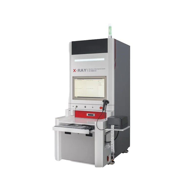
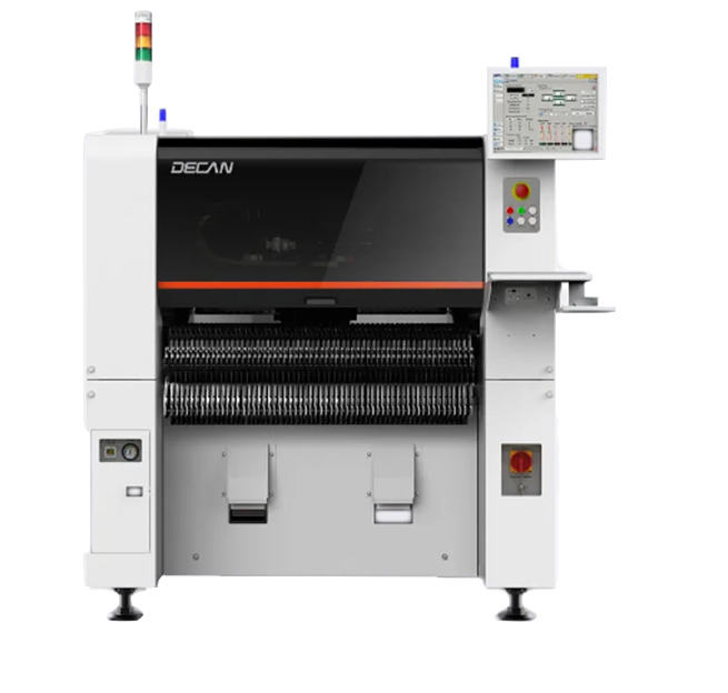
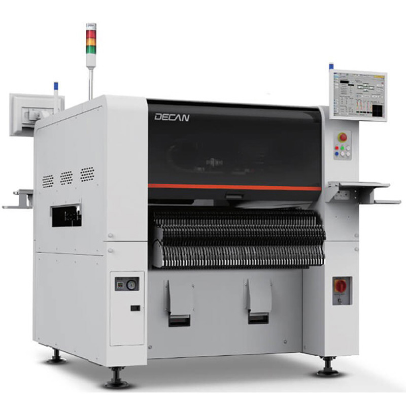
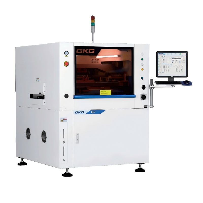
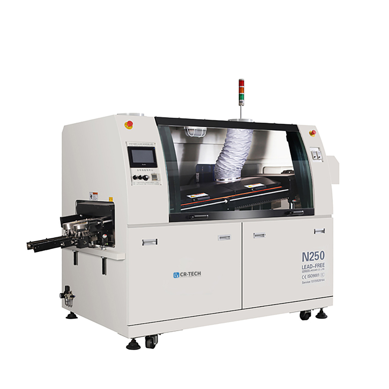
Machines Used: Automatic Insertion Line + Selective Soldering + AOI
The Customer’s Challenge
A mid-sized German manufacturer of industrial automation controllers was struggling with high defect rates in their THT assembly process. They were using manual insertion and wave soldering, resulting in:
-
15% rework rate due to solder bridges and missing components
-
Long changeover times (up to 3 hours) between product batches
-
Inconsistent solder joint quality on low-volume, high-mix boards
They needed a complete THT solution – not just machines – to improve quality and throughput.
Our Solution: End-to-End THT Line Integration
We designed and installed a full THT one-stop production line optimized for high-mix, medium-volume manufacturing.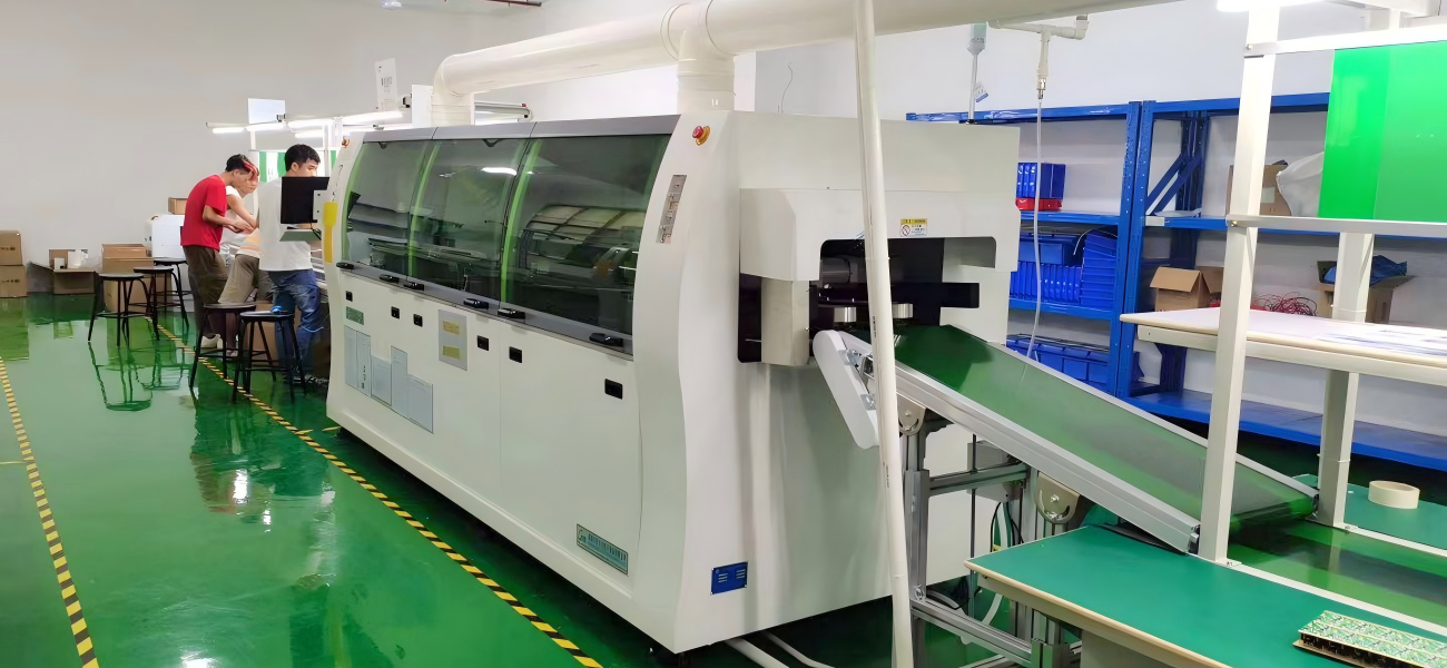
Equipment Delivered:
| Station | Equipment | Benefit |
|---|---|---|
| Insertion | 5 x Automatic Radial & Axial Insertion Machines | 98% placement accuracy |
| Fluxing | Closed-loop Selective Fluxer | ±0.1mm precision |
| Soldering | 3-Zone Preheating + High-Precision Selective Soldering | Zero thermal shock |
| Inspection | Online AOI with THT algorithm library | Catches polarity & bridging |
Key Process Improvements Implemented:
1:PCB fixture standardization – reduced changeover to 18 minute
2:Soldering parameter optimization – developed 12 product-specific profiles
3:Operator training – on-site certification for 4 technicians
The Results (After 6 Months)
|
Metric |
Before |
After |
Improvement |
|---|---|---|---|
| First-pass yield | 82% | 96.5% | +14.5% |
| Rework cost per board | €2.10 | €0.85 | -60% |
| Changeover time | 180 min | 18 min | -90% |
| Solder joint defects (ppm) | 3,800 | 1,200 | -68% |
*"This THT line reduced our warranty claims significantly. The 10-year experience of the supplier showed in the fixture design and soldering profiles – things you don't get from a standard machine seller."*
– Head of Production, Germany
Why This THT Solution Works for Your Factory Too
-
One-stop responsibility – one contract, one installation team, one support line
-
Designed for mixed batches – no more wave soldering setup nightmares
-
Proven ROI – most customers pay back in < 12 months
📞 Contact us for a free PCB sample soldering test. Send your Gerber files and we will show you the result.


